
The Main Circuit Breaker For This Control Panel Doesn’t De-energize The Panel
Introduction
This control panel is like thousands of control panels out in facilities today, and maybe even many in your facility. It controls a machine on the factory floor. It has four motor starters, individual circuit breakers for those motor circuits, ice cube relays, small fuses, and a control transformer. And on the door there are pushbuttons, indicating lights, rotary switches. In the lower right
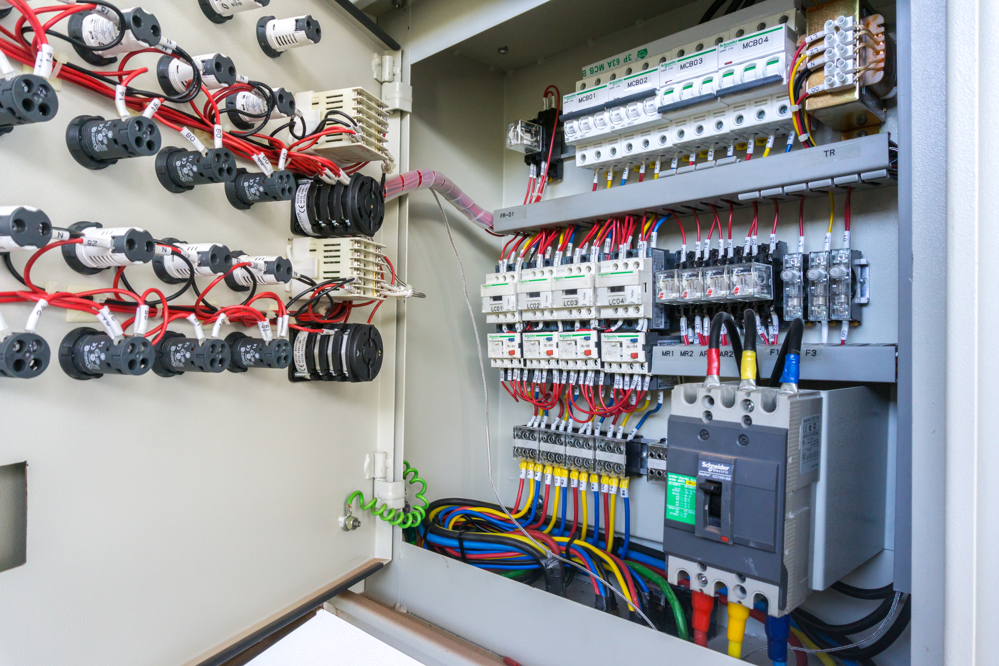
corner of the panel is the main circuit breaker. With the door closed, we can still operate the breaker through the hole in the door. Pretty typical of many control panels. The question is how do we de-energize this panel to establish an electrically safe work condition.
Circuit Breakers
Circuit breakers have a line and load side. The line side is where the incoming power is connected. The load side is where the downstream loads are connected. In this case, the downstream loads are everything else in this panel and all of the motors and other components in the control circuit outside the panel. Everything downstream from this main breaker is being protected from over-currents by this breaker.
The question is, does this circuit breaker de-energize this panel? The answer is no. Opening this breaker de-energizes everything in this panel as well as the downstream loads, everything except for the line side of the breaker itself. When this circuit breaker is opened, turned off, the line side of the breaker is still hot. With the line side still energized by the incoming power, the panel has to be considered energized because the main breaker still has a shock and arc flash hazard. You could not use this breaker to establish an electrically safe work condition for this panel.

Electrically Safe Work Condition
To properly de-energize this panel to establish an electrically safe work condition, you would need to locate the circuit breaker or disconnect that feeds power to your control panel. Your lockout tagout procedures should indicate the location of this breaker or disconnect. Once that is found you would open that disconnect or circuit breaker and apply your locks and tag. Return to the control panel and follow through with all of the required lockout tagout procedures. The most important of which is the live-dead-live test to verify zero voltage. Always Test-Before-Touch. And of course, always wear the required PPE while verifying zero volts. Every circuit has to be considered energized until you’ve proven it’s not.
Troubleshooting Example 1
As a troubleshooting example, let us use a situation in which the operator of this machine reports that one of its four conveyors stopped running. You show up and ask the operator what led up to this problem, and they state that that conveyor has been making a lot more noise than usual. A squealing sound. You suspect a mechanical problem, and on an inspection of the conveyor pulleys, it is evident that a bearing has failed thus causing too much load on the motor. Next, we go to the control panel and see that it has an arc flash label that states an arc flash rating of 11 cal/cm2 and a voltage of 480. We must don the appropriate PPE to protect you from such an arc flash and voltage. Because we are only going to do a visual inspection and we are wearing the proper PPE we can proceed. We do an orderly shutdown of everything the panel controls then open the main breaker. We then open the control panel door and see that the motor starter has tripped for that motor. Everything else in the panel appears fine, we reset the motor starter, and close the door. We place our lock and tag on the main breaker, and we perform all other procedures required by our lockout tagout procedures and proceed to repair the bearing.
Troubleshooting Example 2
In the next example, the operator reported the conveyor wouldn’t turn on. There was no mention of a squealing noise. During our initial troubleshooting, we attempt to turn on that conveyor manually and we hear the motor starter turn on, or pull-in as we say, inside the cabinet. But, the conveyor is still not moving. We don the appropriate PPE, open the control panel door and begin our visual inspection of the panel. We immediately notice the motor starter for conveyor four is showing signs of heat damage. A dark smoke-like film is on the area covering the motor starter contacts. This, we know from experience, is an indication of poor contact being made by the starter contacts. The other starters don’t show this damage. Now we know we are going to have to remove and replace the starter or at least disassemble it for inspection and repair. In either case, we’ll need to completely de-energize the panel. At this time we’ll need to close the control panel door and open the main breaker. We then must go to the upstream circuit breaker for this panel, turn it off and apply our lock and tag. Upon returning to the control panel, wearing the appropriate PPE we open the control panel door. Using an appropriate volt-meter, we test that meter on a known live circuit, then measure incoming line leads phase-to-phase and phase-to-ground and do verify that we indeed have zero volts. We then retest the meter on a known live circuit to confirm the meter is still working. That is the Live-Dead-Live test. Now we can remove the PPE and begin our repair work. We find the contacts badly damaged from not making proper contact and the carbon buildup inside the starter is preventing the contact assembly from moving freely. We replace the motor starter, and now all conveyors are working fine.
A Shield May Not Work
Some people have suggested that if you add a plastic or metal shield to the main breaker that covers the energized line leads that should solve the problem. It actually can create a whole new problem. OSHA requires electrical equipment to be “accepted, or certified, or listed, or labeled, or otherwise determined to be safe by a nationally recognized testing laboratory.” Underwriters Laboratory is such a lab. If you add a plastic or metal shield to your breaker, it is no-longer UL Listed because it didn’t have your shield when tested. The shield could cause the breaker to operate differently than when it was manufactured and tested, resulting in an unsafe situation.
Control Panel Design
This next piece of advice doesn’t help you with existing control panels but could make your future panels safer and easier to work with where 70E is concerned. That advice is to ask the OEM of your new panels to put this main breaker in a separate box on the side of the panel. Putting the main circuit breaker in a separate enclosure is becoming quite common now, and manufacturers of these boxes are offering this option. Hoffman’s SEQUESTR™ line of enclosures is one such offering.
Circuit Breaker Panel Boards
I used a control panel as an example here, but all of this applies to circuit breaker panel boards as well, not just control panels. Opening the main breaker of a circuit breaker panel does not establish an electrically safe work condition. If you’re going to add a circuit breaker, for example, turning off the main breaker for the panel board is not sufficient. You will need to open the circuit breaker that feeds this panel to establish an electrically safe work condition.
Conclusion
In conclusion, it is essential that we know what does and what does not make an electrical panel electrically safe. It must be spelled out in your lockout/tagout procedures which disconnect, or circuit breaker removes power from the equipment that will enable us to create the electrically safe work condition. We will wear the appropriate PPE any time the equipment has an energized circuit component above 50V.


You must be logged in to post a comment.